The hardware controlling the opening and closing of the dome shutter relies on a limit switch on either end to signel when the shutter is open or closed. Normally, these switches are considered “something that never breaks”. However, the truth is more like “something that seldom breaks” - and in my case it did, causing a night of FUD : Fear, Uncertainty and Doubt! Additionally, I had to confess that I, or rather my observatory, was the culprit when people started asking in the local facebook group, if anyone knew what the terrible noise around midnight was!
To top it off, my neighbor was the one waking me up, letting me know that my observatory was going crazy.
The reason turned out to be a defect in the limit switch that was supposed to signal that the shutter was closed. Without this signal the rather powerful electromotor kept running, but since the shutter could not close any more than it already was, the gears just started grinding with a terrifying loud noise.
What’s the plan?
Obviously I had to replace the limit switch, but by now I knew that if it could fail once, it could fail again - so I decided that it had to be made redundant.
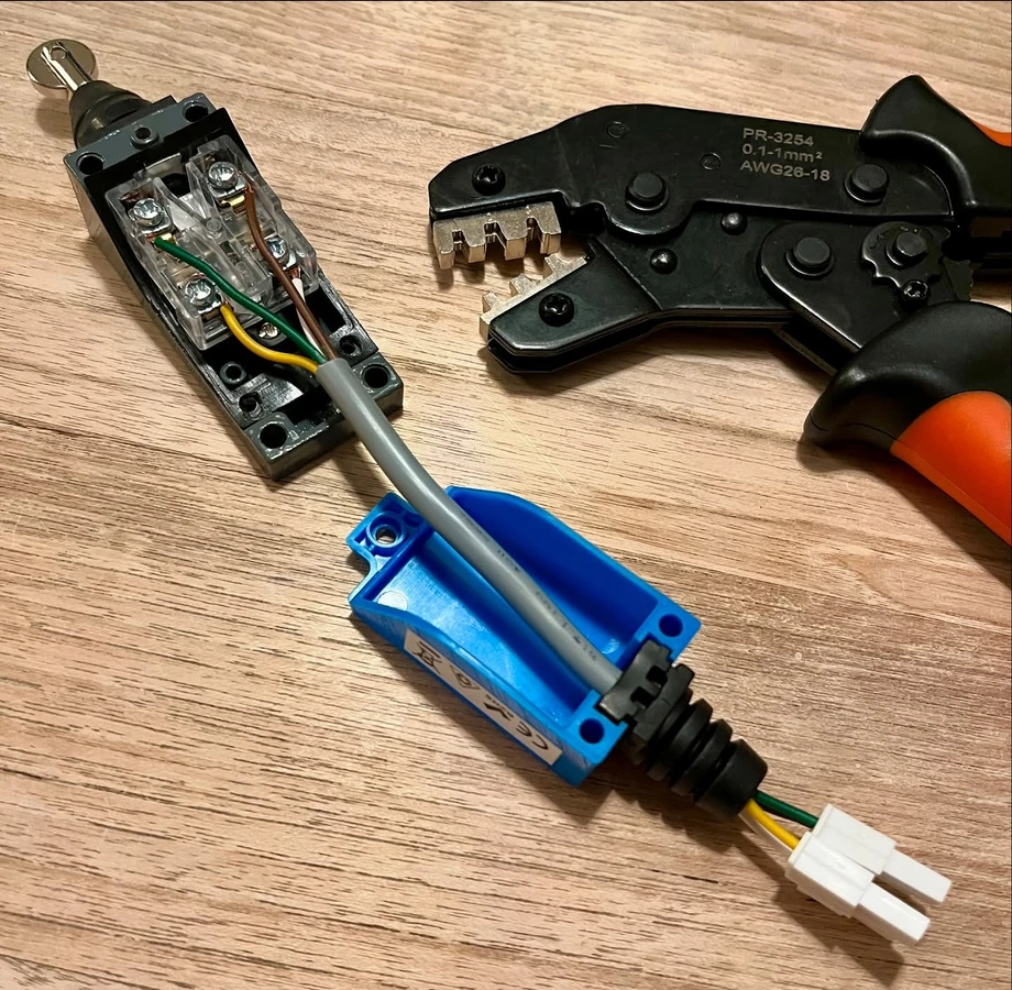
After reading through schematics of the dome wiring, I figured out how to add a secondary limit switch. These typically come with 2 circuits: A NO (Normal Open) and NC (Normal Closed) - this allows the same limit switch to both be able to physically cut power to the motor when it is closed (using the NC circuit) and signal to the controller what state it is in (using the NO circuit).
So I decided to add the secondary NC circuit in serial with the primary (ensuring that if either one was closed power would be cut) while leaving the NO circuit independent. This allowed me to add a small wireless Raspberry PI that reads the state of the secondary limit switch.
This way, I can compare the state of the primary and secondary, and if they differ I’ll know that at least one of them has become defective. …
Implementation
I added a simple read circuit between GND, Power and a GPIO pin on the RaspberryPi:

With this basic circuit, it is simple to read the state using Python on the R-Pi:
	#!/usr/bin/python

	import RPi.GPIO as GPIO
	import time

	# Vælg BCM nummerering
	GPIO.setmode(GPIO.BCM)

	# Sæt den GPIO port du vil aflæse (her fx GPIO 22) op som input
	# Med en pull-down modstand, så den går til LOW når der ikke er signal
	GPIO.setup(22, GPIO.IN, pull_up_down=GPIO.PUD_DOWN)

	try:
	    while True:
	        # Læs status på GPIO 22
	        status = GPIO.input(22)
	        if status:
	            print("GPIO 22 er HIGH (tændt)")
	        else:
	            print("GPIO 22 er LOW (slukket)")
	        time.sleep(1)
	except KeyboardInterrupt:
	    print("Programmet stoppes.")
	finally:
        GPIO.cleanup()  # Ryd op i GPIO-indstillingerne
This is the current state of the redundant shutter-close limit switch. The physical cutting of power to the motor is now redundant, the R-Pi is in place to allow independent reading of the limit switch state. Currently I am working on a generalized ACIS (Astrografen Control and Information System) service that will combine diffent safety readings into an ASCOM Alpaca SafefyMonitor device, that will be used by the software controlling image acquisition.